From the Start menu, desktop shortcut or AppsAnyWhere open Revit.
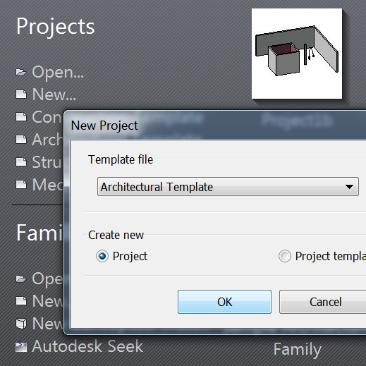
From the Welcome window, under Projects.
Select: New...
and choose the Architectural Template (the units are mm).
Or
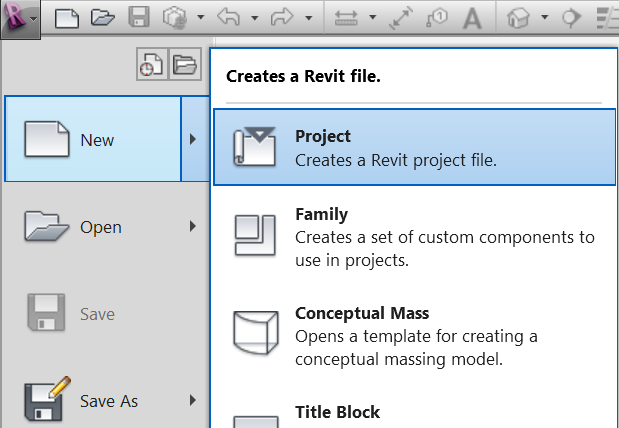
From the Revit application menu (Big
R)
Select New - Project - Architectural Template (the units are mm).
Both of these will:
Create a couple of levels and four elevation views.
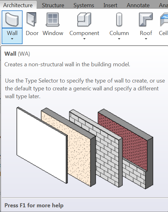
Select the wall drawing tool from the Architectural elements tab
or sometimes (depending on the version of Revit) the Home tab.
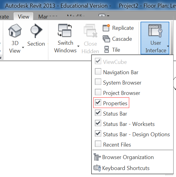
If the wall properties box is not visible, tick it in the User Interface list.
The Project Browser (above the Properties check box) is also worth switching on.
It allows floor plans and elevations to be selected.
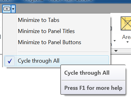
If the panel containing the User Interface is not visible, click on the icon shown or select from the small pull-down menu alongside.
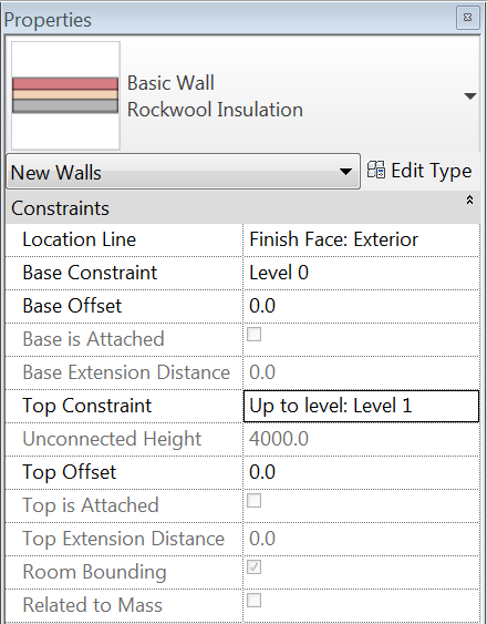
Before drawing a wall, choose the Location Line, Base Constraint and Top Constraint from the properties box.

The wall construction can also be modified from Edit Type.
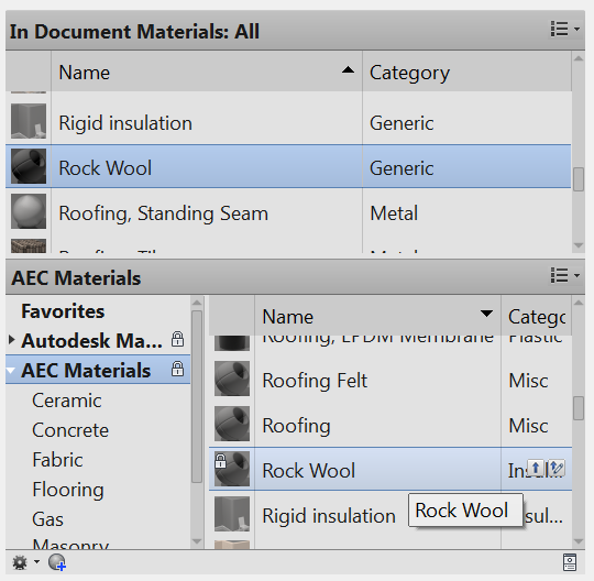
Materials can be chosen, their thicknesses changed and their colours selected.
Images can also be used for material finishes allowing wall paper to be placed on a wall.

Walls will be drawn based upon the settings chosen in the wall properties box,
and the lengths drawn or typed.
Hold the shift key to constrain to 90° angles.
Floor slabs are added by defining the edges with the modify tools.
The default tool is the wall picker.
When you are in sketch mode for floors or roofs, the main drawing will be grayed out and the only way to exit this mode is through the Modify tab.

Either cancelling with the red cross or accepting with the green tick.
The escape key will not work.
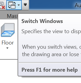
Switch to the 3D window,
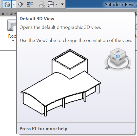
create a default 3D view or

a perspective camera view, from the pull-down menu next to the 3D icon.
The small camera icon locates the view point,
with a field, and depth of view, specified by the second click of the mouse.
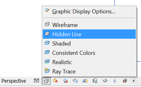
The visual display style can be chosen from the Graphic display options.
As well as allowing views to be orbited around.
(Shift scroll button)
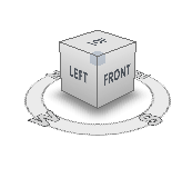
Clicking on a face of the View Cube will show an elevation or plan.
Clicking on an edge will give a 45 ° view.
Whilst clicking on a corner will show an isometric.
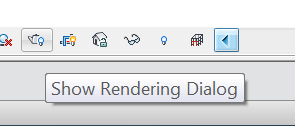
Render settings can be selected once the render (teapot) icon has been clicked
from within the 3D window.
RevitCity is a source of components to be used in your design.